From our lab: the first images
What does programmable phase modulation look like in practice? IN-VISION´s optical engineers assembled a deliberately simple test setup. Here are some of the first results.


A quick note before we begin: the following images are far from perfect.
They are not polished, Instagram-ready technology shots. They show what optical experiments actually look like — including visible diffraction artefacts, speckle and a fog machine borrowed from the last IN-VISION Christmas party.
That is precisely why the images are useful. They make the basic capabilities of phase light modulation surprisingly easy to see.
We change the focus by software. The distance between the left and the right side of the picture are about 20cm. The blurriness in the video is caused by MPEG compression.
1. Freely programmable focus
A large depth of focus normally comes with a familiar optical trade-off. Closing the aperture increases the depth of field, but reduces the amount of light transmitted through the system.
PLM offers another approach. Instead of trying to keep every distance in focus simultaneously, the focal plane can be moved electronically by changing the phase pattern displayed on the chip.
In our demonstration, the same Mickey Mouse image is first focused on the rear plane and then on the front plane. Nothing in the projection setup is mechanically repositioned. Only the phase pattern changes.
The static photographs also reveal that the shape of the projection cone can be modified significantly.
Because the image is produced through diffraction, the optical path contains higher diffraction orders and speckle. These effects are clearly visible in the experiment. They can be reduced through better computer-generated hologram algorithms, appropriate Fourier-optical filtering and further optimisation of the illumination and projection setup.
The important result at this stage is not a flawless image. It is the ability to place the focus through software.
2. Beam Steering by Software
What looks a little like event lighting demonstrates how a beam of light can be steered using the PLM chip. You see the same setup with completely different shape light cones. Instead of a large scanning mirror moving along several degrees of freedom, the two million micromirrors of the DLPM980 perform this task.
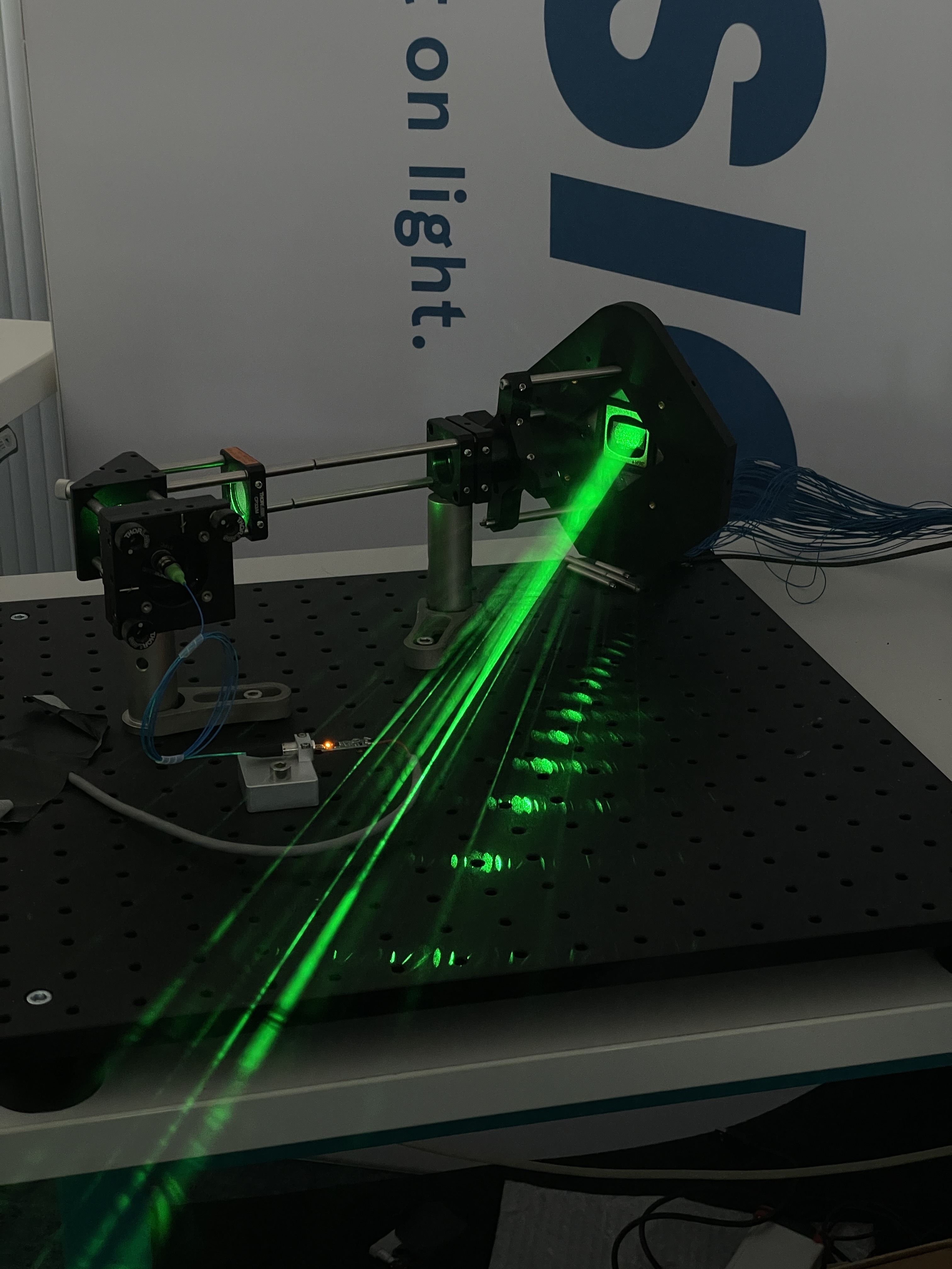
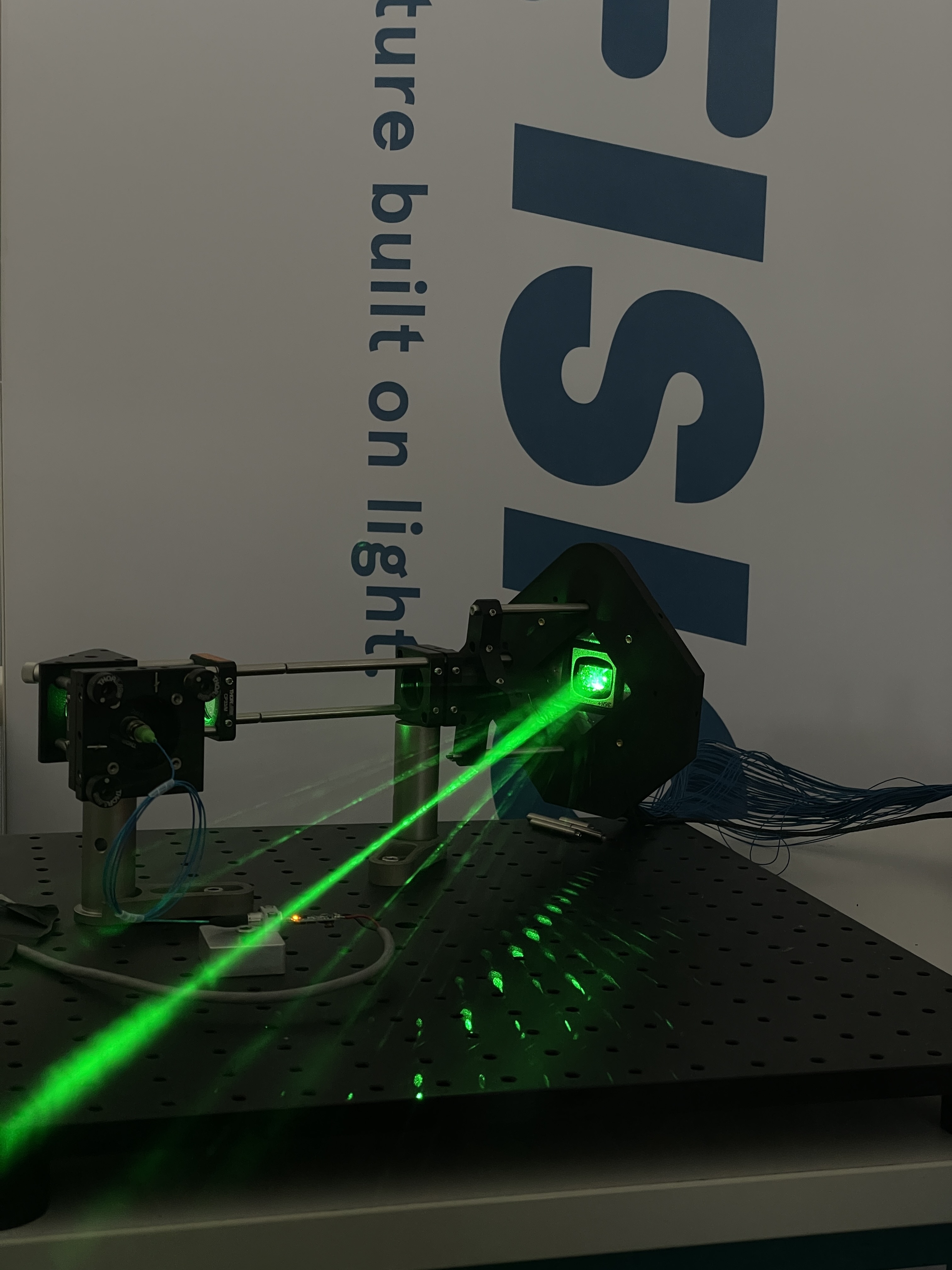
Being able to control every single micromirror without any crosstalk at a level of 16 steps, gives us a programmable diffraction grating digitally programmable. This enables us to not control the image plane, but to control any imageplane after the PLM-chip. We control the whole Light-Field.

3. Structured optical energy instead of flat projection
We use the PLM first to illuminate the entire projection area and then to focus the light increasingly tightly onto a single point. Even with the naked eye, it is easy to see how the intensity continues to increase.
- The optical power is therefore distributed across the illuminated areas in the image.
The images show phase-modulated light generated with the DLPM670VIS.

Our Test Setup, based on the DLPM980VIS Development Kit
4. Our Test Setup
We kept the test setup very simple. It uses the DLPM980VIS Development Kit for wavelengths from 420–680 nm, featuring a 0.98-inch device with a resolution of 2048 × 1088 pixels. It has an onboard FPGA with IN-VISIONs Software, which enables you to integrate the device in the system of your choice, ranging from a very basic optical setup, by using our GUI, to a highly automated machine integrating the device with our API. The Kit is equipped with optical input and output trigger as well as high speed interfaces to ensure the integration of high speed applications.
The laser light source, breadboard and spacers are standard Thorlabs components; the fully compatible DMD mounting plate comes from IN-VISION. All together can be also purchased from IN-VISION – just contact us to receive an offer.
To demonstrate the function of the PLM chip more clearly, we project directly from the DMD without any additional optics. And yes, we cheated a little: we used the fog machine left over from the last Christmas party to make the beams more visible.